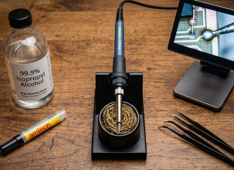
Welcome to Smiggy's electronics repair basics! Whether you are restoring vintage microcomputers, fixing a worn-out trace on a PCB, repairing household gadgets, or assembling a fresh electronics kit, soldering is the single most essential skill on the workbench. Here in my Rainhill workshop, a soldering iron is warm on my bench almost every single day.
Soldering isn't black magic; it's a mechanical and metallurgical connection built on heat transfer and cleanliness. Once you master the fundamentals of temperature control, flux application, and joint geometry, you’ll be making reliable, professional-grade repairs every time.
1. Choosing Your Iron & Bench Gear
Your iron is your primary tool. Using a cheap wall-plug soldering iron with no temperature control is one of the fastest ways to lift pads, scorch PCBs, and ruin components.
Recommended Irons
- Stationary Workhorse: A temperature-controlled station is ideal for dedicated workbench use. I use a Hakko FX-888D—it heats up fast, holds a steady temperature, and offers a huge variety of genuine Hakko tip shapes. The Weller WE1010 is another solid bench contender.
- Portable & Smart Irons: The Pinecil (BB2) or TS100 / TS101 USB-C powered smart irons are exceptional. Running on open-source firmware (IronOS), they offer precise PID temperature control in a tiny form factor, perfect for quick fixes away from the main bench.
Essential Tip Shapes
- Chisel Tip (1.6mm–2.4mm): The best all-rounder. Provides maximum surface area for fast thermal transfer to both the pad and the component pin.
- Fine Conical Tip: Great for tight spaces, but carries lower thermal mass—don't rely on it for heavy ground planes.
- Knife Tip: Excellent for drag-soldering Surface Mount Devices (SMD) and clearing solder bridges.
2. Essential Workshop Supplies
Having the right iron is only half the battle. Your consumables determine the quality and longevity of your solder joint:
| Supply | Workbench Recommendation |
|---|---|
| Solder Wire | • Vintage/Repair: 60/40 or 63/37 Leaded Rosin-Core (0.8mm / 0.5mm) • Modern/RoHS: SAC303 or Sn99.3/Cu0.7 Lead-Free Solder |
| Flux | Tack flux (e.g., Amtech NC-559) or a quality No-Clean Flux Pen |
| Desoldering | Copper braid/solder wick + High-vacuum mechanical solder sucker |
| Cleaning | Brass wool tip cleaner & 99.9% Isopropyl Alcohol (IPA) |
Smiggy’s Tip on Solder Choice: Leaded 63/37 (eutectic) solder melts instantly at 183°C (361°F) without passing through a semi-solid "pasty" state, making cold joints far less likely. If working on modern lead-free gear, bump your iron temperature up slightly to handle higher melting points (~217°C/422°F).
3. Step-by-Step: Anatomy of the Perfect Solder Joint
According to IPC-A-610 (the global standard for electronic assembly acceptability), an ideal through-hole solder joint should feature a smooth, shiny surface with a concave fillet—resembling a tiny shiny volcano.
  Ideal Joint Fillet (Concave)         Cold / Defective Joint (Bulbous/Dull)

          / \  <- Smooth Fillet                (   ) <- Dull Blob
         /   \                                (     )
  ======[=====]====== Pad              ======[=====]====== Pad
           |                                     |
         Lead                                  Lead
The Smiggy Technique:
- Prep & Clean: Clean the PCB pad with 99.9% IPA to remove oxides, oil, and dust.
- Tin the Tip: Wipe the hot tip in brass wool, then apply a small bead of fresh solder to ensure good thermal bridge contact.
- Heat Both Surface Elements: Touch the flat side of your chisel tip so it simultaneously contacts both the component pin and the copper PCB pad. Hold for 1 to 2 seconds to bring both to temperature.
- Feed Solder into the Joint: Flow fresh solder into the junction opposite the iron tip (feed into the heated joint, not onto the tip).
- Remove Heat: Remove the solder wire first, then lift the iron straight off.
- Cool Naturally: Allow the joint to solidify undisturbed for a few seconds. Never blow on the joint to cool it, as rapid forced air creates internal micro-cracks.
4. Troubleshooting Common Beginner Mistakes
- Cold Solder Joints:
- Appears as: Dull, grainy, or craggy surface with poor mechanical strength.
- Cause: Component or pad wasn't brought to full reflow temperature, or moved during cooling.
- Fix: Apply liquid flux, reheat with a clean iron, and allow to set undisturbed.
- Solder Bridges:
- Appears as: Solder spanning across adjacent PCB pins, creating a short circuit.
- Fix: Apply flux to the bridge and pull the iron tip down through the pins. Excess solder will follow the heat, or can be pulled off using copper desoldering wick.
- Lifting Copper Pads:
- Cause: Applying too much physical pressure or holding extreme heat (>400°C) on a pad for too long, melting the underlying epoxy adhesive.
- Fix: Be gentle! Let thermal conductivity do the work, not physical force.
5. Recommended Video Tutorials
Seeing heat transfer in motion is the fastest way to build muscle memory. Here are three highly recommended tutorials covering basic through-hole and SMD techniques:
- EEVblog #180 — Soldering Tutorial Part 1 (Through-Hole):
Dave Jones breaks down thermal transfer, tip selection, and joint geometry in an easy-to-understand format.

Watch EEVblog's Through-Hole Soldering Guide on YouTube - Pace Basic Soldering Lessons (Classic Series):
Originally produced for industrial training, Pace's video series remains the gold standard for visual explanations of wetting action, flux dynamics, and heat bridges.

Watch Pace's Basic Soldering Guide on YouTube
6. Official Standards & References
If you want to dig deeper into professional workmanship standards, check out these industry benchmarks:
- IPC-A-610 Standard: Acceptability of Electronic Assemblies. The definitive global quality standard for commercial, industrial, and aerospace electronics assembly.
- NASA-STD-8739.3: NASA Workmanship Standard for Soldered Electrical Connections. Detailed specifications on high-reliability manual soldering procedures used on spaceflight hardware.
- Kester Solder Reference Manual: Guides on flux chemistry (Rosin Mildly Activated vs. No-Clean vs. Water Soluble) and eutectic alloy behaviors.
Summary Checklist for Your Bench
- Safety First: Always wear safety glasses and work in a well-ventilated area (use a fume extractor for rosin fumes).
- Keep It Clean: Clean PCB surfaces with IPA and keep your iron tip tinned.
- Flux is Your Friend: When in doubt, add flux!
- Inspect Your Work: Use a jeweler's loupe or digital microscope to verify full 360-degree joint wetting.
Happy tinkering, and stay tuned for more workbench repair guides from the Rainhill shop!
Comments (0)
No comments yet. Be the first to comment on Smiggy's article!
Leave a Comment